Wireless Token Ring Protocol (WTRP)
This whitepaper looks at the Wireless Token Ring Protocol (WTRP) specified in Annex L of STANAG 5066 to support multi-node communication with HF Radio. It gives a high level overview of the protocol, how it works, and scenarios where it is most appropriate, particularly Naval task groups.
It looks at how WTRP works in a deployment, tying this to the WTRP implementation in Isode’s Icon-5066 product.
Introduction to WTRP
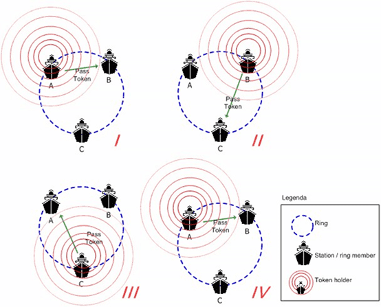
When nodes communicate over a shared radio channel, it is important that only one node communicates at a time. WTRP achieves this by passing a token between nodes and requiring that only the token-holder transmits. This is illustrated in the diagram above, which is taken from the STANAG 5066 standard. The transit path of the token is referred to as a “ring”, although we will see later that a ring topology is not always used.
When a node transmits, it passes the token to the node which will transmit next. At the same time, the node can transmit application data to any node in the ring. So in parallel with the token moving around the ring, unicast or multicast communication can take place between any members of the ring.
Point to Point vs Multi-Point
A common way to use an HF Channel is to communicate between a single pair of nodes. This will typically be done using ALE (Automatic Link Establishment) to select an available frequency that propagates. A key benefit of point to point communication is that use of the HF channel can be optimized for the pair of active nodes, rather than needed to make compromises across multiple nodes. Given the variability, high error rate and general difficulty of an HF channel it will often make sense to use point to point.
The main downside of point to point is channel sharing. A typical Mobile Unit (MU) can only support access to a single channel. There are some scenarios where this is fine:
- If use of the HF channel is primarily to communicate between MU and shore, the MU can effectively dedicate the HF channel for this purpose.
- If the overall network is lightly loaded, it is fine for a node to finish communicating with one peer before starting to communicate with another.
However in a busy network, communication between a pair of nodes can block other nodes from communicating with either of the nodes. This means that communication cannot take place in a timely manner, which can lead to excessive delay, which might be considered an effective denial of service. To avoid this, a multi-point network can be used, with multiple nodes actively sharing the same channel.
WTRP vs CSMA
STANAG 5066 defines a Media Access Control (MAC) sub-layer to enable multiple nodes to share a single channel. It specified two protocols that can support this: WTRP in Annex K and Carrier Sense Multiple Access (CSMA) in Annex L.
Collision Detection is not possible in an HF channel, so the familiar CSMA-CD model cannot be used. Annex K provides two models to avoid collision:
- Slotted. Each node is assigned a slot, so that after a transmission each node will wait for its slot. This is a robust approach, suitable for a small number of nodes. It is “unfair” in that nodes with early slots will get priority.
- Jitter. Each node waits a random time to transmit, with the parameters chosen for the size of network and typical traffic levels. Care is needed to tune this, as “short” parameters will lead to collisions, which are slow and difficult to recover from, an “long” parameters will lead to undue overhead.
There is an optimization that will eliminate delays when only a single pair of nodes is communicating. This improves performance, but at the expense of fairness.
CSMA is a simple approach which is often a good choice, particularly for lightly loaded networks. The downsides are:
- Delays arising from the mechanisms increase overhead and reduce overall throughput.
- The better performing options are not fair, which is of particular concern as load increases.
- There is risk of collision, which is highly undesirable.
WTRP addresses these downsides. While WTRP is often the best choice for multi-node networks, there are scenarios where CSMA is preferable, particularly for lightly loaded networks.
History of WTRP
The original design of WTRP was based on work by Mustafa Ergen, Duke Lee et. al., “Wireless Token Ring Protocol”, University of California, Berkeley, CA 94720, USA. This specification can be considered as the original WTRP.
WTRP first appeared in Edition 3 of STANAG 5066. Many aspects were the same as the original, but a number of changes were made to make the protocol more suitable for HF. In particular, the protocol was adapted to support partially connected networks.
Detailed analysis of Edition 3 exposed serious problems with the protocol specified, although the high level model was good. The support for partially connected networks was unworkable and the general protocol overhead was too high. This has been addressed in Edition 4, and this paper considers Edition 4 only.
Edition 3 only addressed fixed speed, which is a significant issues for HF, where speed can be highly variable. This is particularly important for Surface Wave, a key WTRP target, where maximum speed will decrease systematically with distance. Edition 4 addresses this.
Deployment Scenarios for WTRP
Sky Wave
Sky Wave is the best know HF propagation, with transmission bouncing off the ionosphere. Use of point to point is often the best choice for Sky Wave, as the high variability of the channel makes it preferable to optimize pair-wise, and to operate one pair at a time. However, there can be scenarios where WTRP is a good choice for Sky Wave.
Consider a setup with two Mobile Units (MUs) where they communicate with a ground station and it is desired to use a single Rx/Tx subsystem on the ground. Where an HF frequency can be chosen that is expected to be reasonably reliable for communication with the MUs, use of WTRP is good way to enable the channel to be shared in an efficient and fair manner.
Surface Wave
HF also propagates as Surface Wave, providing communication significantly beyond line of sight. This works particularly well over water and so is often used for Naval communication between ships. Surface Wave gives a more reliable and predictable communications channel than Sky Wave. An important characteristic is that the channel quality, and so maximum viable speed, decreases with distance between two nodes.
WTRP is particularly useful for communication within a Naval task group, and it is not a coincidence that ships are used in the STANAG 5066 diagrams. WTRP allows a group of ships to share a single channel and to transmit in turn, without excluding any ship. This makes Naval task group communication a key target for WTRP use. As ships move apart, it is important to reduce speed to match link quality.
WTRP in Practice
This section looks in more detail at how WTRP works, with examples taken from Isode’s Icon-5066 product. Screenshots of ring monitoring show an operator-oriented view of WTRP.
Normal Operation
A WTRP node needs to listen to other nodes in the ring, defined as “promiscuous mode”. This means that a node can track the token as it moves around the ring, as shown in the screenshot above of a part of the Icon-5066 Web monitoring UI. This enables an operator to visualize the ring and to observe token progress around the ring. Each node cycles through three states:
- Have Token (HVT). Here the node has the token. This gives the node the right to transmit data to any other node, noting that data can be sent to multiple other nodes. During this transmission, the node will pass the token on to the next node in the ring. This is shown as the red arrow in the diagram. In the screenshot above, the WTRP 1 node being monitored has the token and is part way through a transmission to node WTRP 3 to which the token is being passed.
- Monitoring (MON). Once a node has transmitted a token, it will listen for the next node transmitting. If it does not hear this, it will transmit the token again, possibly to a different node. In the above screenshot, WTRP 1 has transitioned to MON state and is listening for WTRP 3, which should have the token, to transmit it.
- Idle (IDL). When a node has determined that the token has been passed, it will move to Idle state and wait to receive the token again. It can monitor the token being passed around the ring. In the above screenshot, WTRP 3 is attempting to pass the token to WTRP 4 and WTRP 1 has entered IDL state.
This is the normal mode of operation, and a node will commonly be in a ring and following this transition sequence.
Ring Formation & Building
When a node is not in a ring and detects an existing ring, it will wait to be invited to join the ring. From time to time, nodes in a ring will pause passing the token and send and invite message for new nodes to join. The screenshot above shows a four node ring which the local node (WTRP 1) is not a member of. However, WTRP 1 has just received an invite, and is in SRP (Solicit Reply) state which will lead to it joining the ring.
When a node does not detect another ring, it will after a suitable delay, declare itself to be a “self ring” and invite other nodes to join it. This enables multiple disconnected nodes to find each other.
From time to time, each node in a ring will invite other nodes to join. This can be seen in the screenshot above where the local node (WTRP 1) is in Soliciting (SLT) state, indicating that it has broadcast an invitation and is waiting for other nodes to respond.
Partially Connected Networks
It is possible, particularly with surface wave deployments, that nodes in a “ring” cannot see all other nodes. A simple example is “three ships in a line” scenario where the middle ship can communicate both of the other ships, but the two end ships are too far apart to communicate directly.
WTRP is designed to deal with partially connected topologies. The above screenshot show the middle node view of three nodes in a row (WTRP 1), which is in between WTRP 2 and WTRP 3. You can see that the token is passed to each node in turn, and then comes back to the middle node. In the screenshot, the token is received from WTRP 3, passed to WTRP 2 and then back again (rather than going round in a ring).
The second screen shot shows the view from the end node. The WTRP 3 end node exchanges token with the middle node (WTPR 1). It can infer the existence of the third node (WTRP 2), as the middle node (WTRP 1) transmits the token to it, but it does not hear the third node (WTRP 2) transmitting the token back to the middle node.
WTRP can support arbitrary connectivity of nodes.
Varying Distance and Speed
As (surface wave) nodes move further apart, the SNR (signal to noise ratio) decreases and transmission speed needs to be reduced. For data transfer, STANAG 5066 shares information on maximum recommended speed based on SNR measurements, so the recommendation is made to the sending node for transmission to the receiving node. This enables optimization of data transfer between a pair of nodes.
When a WTRP node transmits, it may send data to multiple nodes at the same time. When it does this, it needs to consider the recommended transmission speed for all nodes, working on the basis of the node with lowest recommended speed.
WTRP contains a second mechanism, which is the Table message that contains information of recommended speeds for all nodes that it can hear, providing a subset of the data rate selection information. This is important for two things:
- To support speed selection for transfer of the token to a node where no data transfer is occurring with the local node (and so no speed recommendations).
- To help determine the best ring topology, including direction of flow. This information is needed to optimize performance.
Change, Failure and Recovery
WTRP has a robust design, which works hard to transfer the token to other ring members, with repeated attempts and varying choice of target. If a node (surface wave) is moving away from other ring members, it will eventually fail to communicate. There can be other reasons why a node will suffer extended communication failure. In these situations, a node will simply drop out of the ring and subsequently seek to detect and join a ring.
A special case that can occur it where two rings form, perhaps initially too far apart to “see” each other. WTRP addresses the situation where such rings detect each other and it enables ring merging.
Transmission Length Choice
When transmitting data over HF, the key choices are speed, interleaver and how long to transmit for. An immediate picture of WTRP operation might well be to have the token passing quickly around the ring. This view is problematic when considering bulk data transfer. Even the best HF speeds are slow. In order to get reasonable utilization, it is desirable to spend most time transferring data, to compensate for the overhead of circulating the token. So in order to optimize throughput, long transmissions are desirable, quite possible using the 127.5 second STANAG 5066 maximum transmission time.
In a busy network, where each node is transmitting data, this can lead to ring transit time of several minutes, which will cause high latency to applications. In some situations, it will make sense to reduce the maximum transmission time for each node (a STANAG 5066 configurable option). This will improve latency at the expense of reducing maximum throughput and link utilization.
High WTRP latency can significantly increase the time for CAS-1 soft link setup relative to operation over point to point networks. This needs to be considered when choosing timers.
Conclusions
This paper has described how WTRP functions and scenarios where it will be useful. It is of particular importance for Naval HF Surface Wave communication within a task group.
Whitepaper Licensing
Isode whitepapers are licensed under a Creative Commons Attribution-ShareAlike 4.0 International License
![]()
Browse Related Whitepapers
