HF Circuits: Automation & Evolution with STANAG 5066
Configuration and management of HF Radio systems commonly uses the term of “HF Circuit” which reflect an active sequence of components from application to antenna. For a small integrated system, this might simply be choosing between voice and data application to use. For larger systems, there can be a choice of many components, leading to a manual choice of setting up the circuit before it can be used.
STANAG 5066 can be treated as just another component in the communications chain, but this misses out many advantages that STANAG 5066 can bring. This paper examines how the concept of HF Circuit can evolve with the inclusion of STANAG 5066 and lead to increased automation. It also explains why HF Circuits, with operator monitoring and control remain important.
This paper is aimed at those planning HF systems, and those wishing to understand how STANAG 5066 has impacted the design of such systems, particularly large shore systems.
It also considers the behaviour of HF Circuit management tools, such as Isode’s Red/Black product.
The Traditional HF Circuit

HF Circuits are an important concept in systems supporting communication between fixed sites and mobile units. A basic aspect of this is that there are multiple components in the communication chain and it is important to be able to monitor all of the components in an HF Circuit.
A typical shore system, will have many instances of each of these devices. It will be useful to mix and match components to build a communication chain suitable for the target peer. Operators will often need to control components to make suitable settings before the HF Circuit can be used. For example:
- Point directional antenna towards target
- Set power level in the power amplifier
- Set frequency on the radio
- Set waveform and speed on the modem
Traditional applications connect over a serial interface to the crypto and cannot determine whether the HF Circuit is viable. For this reason, the operator needs to control the application. In particular, where an ACP 127 circuit is connected to the crypto, the operator needs to be able to enable/disable the ACP 127 circuit so that data is only sent when the HF Circuit has been fully configured.
Components shown to the right of crypto are “black side” and components to the left are “red side”. Operators will generally sit on the red side, and so monitoring and controlling the communications chain needs communication across the red/black boundary.
Tools for Managing HF Circuits
Isode’s Red/Black product is designed for control and monitoring of this type of HF Circuit. It provides a flexible means to control and monitor devices, based on a device abstract specification and a device driver written for the device.
Red/Black is designed to operate across a red/black boundary, enabling a red side operator to monitor and control devices both on red and black side.
Red/Black will allow an HF Circuit to be set up and then used for communication.
Where ACP 127 is used with Isode’s M-Switch product, Red/Black uses an M-Switch device driver which gives access to the (direct to modem) ACP 127 circuits. This enables Red/Black to show which ACP 127 circuit is used in each configured HF Circuit. It also allows the Red/Black operator to enable/disable each ACP 127 circuit. If the circuit is not automatic, an ACP 127 operator can control use of the circuit.
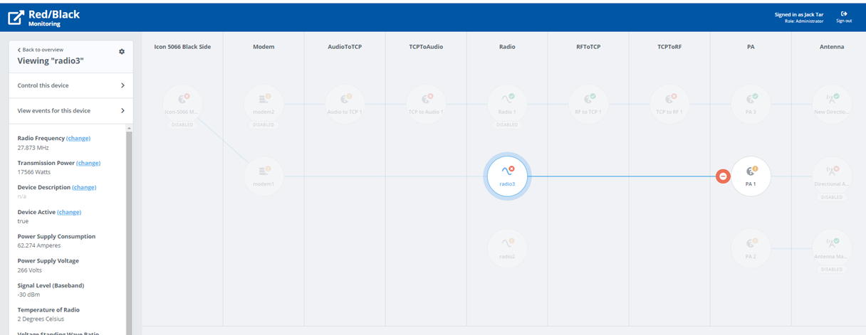
The following screenshot shows Red/Black control of the black side of a communications chain.
Further information on Red/Black is provided in the Isode whitepaper [Red/Black Overview].
How STANAG 5066 Changes Things
STANAG 5066 is a key link level service, which is expected to be used for most data communication in modern HF setups. While it can be added in a simple manner to an HF Circuit, as described in the next section, a much more radical change is needed to gain full advantage. This is described in the rest of this paper.
Simple use of STANAG 5066 in a Circuit

The simple way of adding STANAG 5066 to an HF circuit is shown above. It just becomes another element in the communication chain of the HF Circuit.
This model can be helpful for ACP 127, as it allows STANAG 5066 to be introduced as an optional element in the circuit, so that ACP 127 can be switched between ARQ and non-ARQ (meaning direct to modem with no reliability).
While this approach makes some sense, it doesn’t reflect many of the capabilities provided by STANAG 5066.
Application Multiplexing
STANAG 5066 is designed to multiplex many applications over HF communication. So there are potentially lots of applications that can use an HF Circuit and not just the basic model of a single application being the end of an HF Circuit.
Multi-Node Operation
“Direct to Modem” circuits are generally either:
- Point to point, with direction of traffic under manual operator control; or
- Broadcast, with traffic going in one direction only.
STANAG 5066 can provide this and more. In its simplest use, STANAG 5066 provides ARQ reliable point to point transfer using a link in half duplex mode to achieve this.
Modern STANAG 5066 also provides mechanisms for a single STANAG 5066 server to communicate with multiple peers. This can be simple ARQ point to point communication or multicast using protocols such as ACP 142, which supports both military messaging and email. The multi-destination nature needs to be considered in a modern configuration.
Automated use of ALE
In a traditional HF Circuit, the operator will select the frequency for an HF Circuit by direct control of the radio. Automatic Link Establishment (ALE) is increasingly used to select frequency. This could be done by an HF Circuit operator running ALE to establish the circuit before enabling application use.
When STANAG 5066 is used, it can drive use of ALE and many STANAG 5066 vendors (including Isode) support this, although it is not currently standardized. It is anticipated that use of ALE will be standardized in STANAG 5066 Edition 4. When this is done, there is no requirement for operator selection of radio frequency.
Waveform/Speed Selection
In a traditional HF circuit, the operator will select the speed and interleaver for transfer. When STANAG 5066 is used, it can control this. This means that control of the modem is handled by STANAG 5066 and the operator does not need to control the modem.
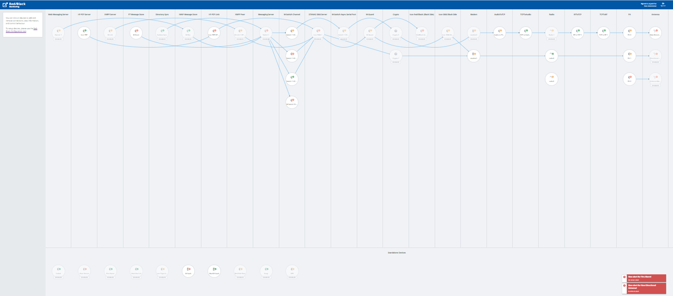
New Model of STANAG 5066 in HF Circuit

The diagram above show the left hand side of a modern HF Circuit using STANAG 5066. There are a number of things to note:
- Many applications share the STANAG 5066 server. The diagram shows a number of critical military applications that use STANAG 5066.
- Although ALE Units are functionally separate from modems, they are generally supplied together and this is how they are shown above.
- Data flow between STANAG 5066 and Modem crosses red/black boundary through a Crypto device.
- STANAG 5066 needs to control modem and ALE, and so crypto bypass is needed. This is functionally critical, but the approach to achieve this is not standardized. Isode’s Icon-5066 product achieves this by use of a pair of XML Guards which can be provided by Isode’s M-Guard product.
- A typical circuit will support a specific set of peers. This might be just a single peer or it may be a set of peers sharing the circuit, using STANAG 5066 mechanisms to enable this. This list of peers is critical, as it impacts (application routing) configuration of the applications, which may be connecting to multiple STANAG 5066 servers, each of which handles a different set of peers. A (small) mobile unit will typically have a single HF Circuit shared by all peers, whereas a shore system will have multiple circuits, possibly as many as one per peer.
- For enabling and disabling circuits, the STANAG 5066 server becomes the key point. If the STANAG 5066 server is disabled, components to the right (towards antenna) can be safely reconfigured. A STANAG 5066 server does not permanently queue traffic, so when it is disabled, it does not store traffic and pending data is pushed back to the application. An application can be safely reconfigured to use a different STANAG 5066 server.
Automation
Introduction of STANAG 5066 into the HF Circuit enables a high level of automation. For a mobile unit, there is likely to be a simple physical configuration which can simply be configured and operate. STANAG 5066 will multiplex applications over the link and use ALE and STANAG 5066 mechanisms to share the link between peers. The requirements for an HF circuit will primarily be monitoring, as there will never be a need for reconfiguration.
Some shore systems with multiple transmit/receive circuits can also be configured with highly stable configurations, which can run fully automated with configuration changes rarely needed, for example to support equipment failure or major reconfiguration. STANAG 5066 provides a means to move to a highly automated data setup.
Why Circuit Control is Still Needed
For some configurations there remains a number of reasons why configuration change needs to be managed in HF Circuits and why elements of HF Circuits need to be controlled.
Three key examples are discussed below.
Antenna and Critical Component sharing
In some situations it is important to use a specific component in an HF Circuit, where that component needs to be shared. Consider a shore system that has a directional transmit antenna, which is being used to support communication with two mobile units in different locations. Each of the mobile units has a STANAG 5066 server configured, so that applications route to a server dedicated to the peer. A circuit needs to be configured and then enabled in turn for each peer, connecting the peer’s STANAG 5066 server to the antenna and correctly pointing the antenna to the mobile unit.
This sort of switching could be done by an operator, or it could be automated based on information on queued data and mobile unit location.
Voice sharing.
While data applications can share an HF circuit using STANAG 5066, the current voice standards require dedicated use of the modem. Where there is a need to share an HF Circuit between voice and data, the modem will need to switch between providing a voice circuit and providing STANAG 5066. This requires HF Circuit reconfiguration.
Regrouping applications
The model of HF Circuits using STANAG 5066 is that a set of STANAG 5066 peers is associated with an HF Circuit. For some systems, this set of peers is going to change. A simple approach is to manage this as part of the HF Circuit.
Often, there is a bigger picture with multiple mobile units moving between different shore stations. Isode’s planned Icon-Topo product will address this scenario, noting that changes made by Icon-Topo will lead to HF Circuit reconfiguration.
Whitepaper Licensing
Isode whitepapers are licensed under a Creative Commons Attribution-ShareAlike 4.0 International License
![]()
Browse Related Whitepapers
