Red/Black Overview
This whitepaper gives an in-depth overview of Red/Black, which is a new Isode product that monitors and controls devices and servers, with a particular focus on HF Radio systems.
Red/Black
Isode Red/Black has three capabilities that distinguish it from the many service monitoring products available:
- It can operate over a secure boundary to enable monitoring and control of devices on the other side of the boundary. A key target, which gives the product its name, is Red/Black separation, which is a term used in cryptographic systems where user data on the Red side is always encrypted before being passed to the Black side.
- As well as monitoring, control of devices is provided. This is not intended to replace general device management, but enables core control of many devices to be provided securely to a single operator. This is particularly important where changes need to be coordinated across multiple devices.
- Communication chains. Red/Black enables devices to be shown following a communication chain where communication depends on a series of connected devices. This can be set to reflect physical configuration. Where connectivity can be controlled by Red/Black, the UI enables operators to change connectivity.
Red/Black provides all this with a clean Web interface that supports monitoring and control of a wide range of device types. The UI for a black side operator is shown in the following screenshot.
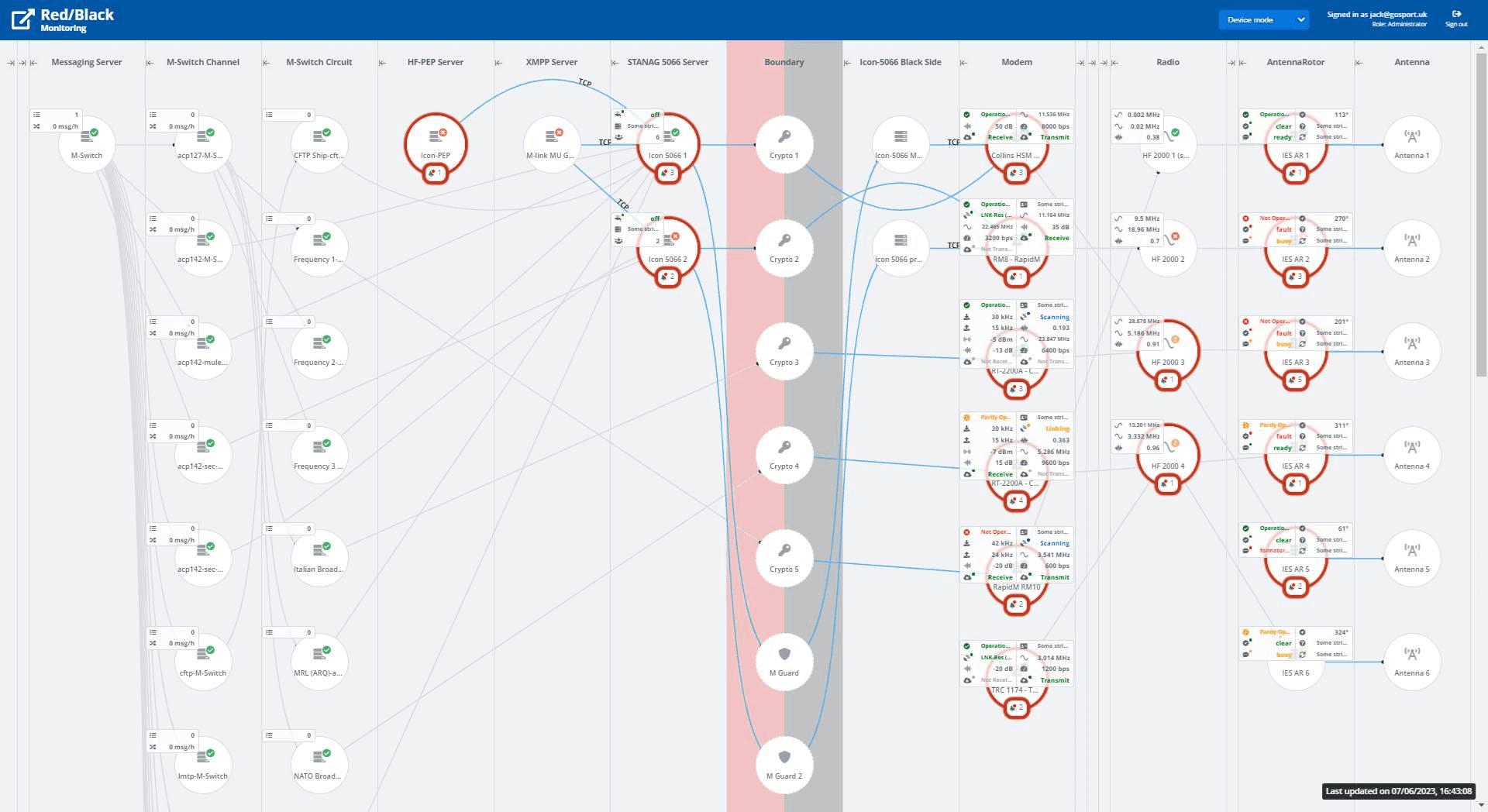
This shows a portion of the UI, reflecting a black side view of a typical set of devices in a black side communication chain, showing how devices are connected. Note that each device shows status with a “traffic light” indication. In a normal operational scenario, you would expect to see all devices “green” and no devices disabled. This gives a clear top level status indication. Devices with unhandled alerts are clearly marked. A number of key parameters for each device are shown, which enables an operator to monitor normal operation of all components from the top screen.
The view of a red side operator is shown in the next screenshot.
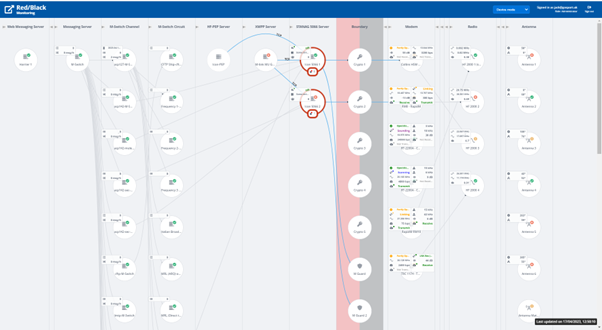
This view enables the red side operator to monitor and control black side devices in addition to services running red side. Devices on the boundary (crypto boxes and guards) are shown as part of the full communications chain.
This supports monitoring and allows operators to disable applications red side so that black side HF devices can be reconfigured safely.
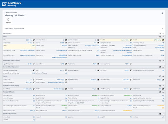
Red/Black provides a detailed view of selected devices with an example in next screenshot.
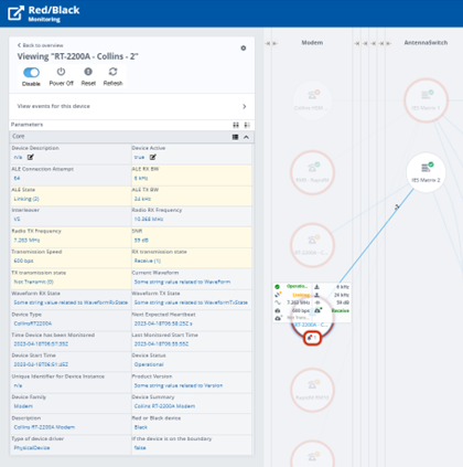
Things to note about the above screenshot:
- Selected device is clearly highlighted, with status and control information on the device shown in left hand column, with options to control the device.
- Devices to which the selected device is connected are shown clearly.
- Parameters are listed, with control parameters modifiable by the operator shown clearly.
- Parameters displayed on top screen (configurable) are shown clearly.
- Device control options, such as enable/disable clearly shown at top of screen.
Monitoring and Control Across a Boundary

A key feature of Red/Black is to provide monitoring and control across a secure boundary. The two sides of the boundary are referred to here as “Red” and “Black” which reflects the terminology used in HF communications deployments. Red/Black could be used across other secure boundaries (e.g., cross domain; organization perimeter) to provide monitoring and control of devices on the other side of the boundary.
Red/Black operates as a pair of servers. The Black side server will control and monitor only devices on the Black side. It will communicate with the Red side server in a secure manner across the boundary, enabling the Red side server to monitor and control the Black side devices. This provides the core separation.
The Red side server can also monitor and control Red side devices. This will allow a Red side operator to manage a communications chain that includes a mix of Red side and Black side devices. This is important for HF communications, where managed devices reside on each side of the Red/Black boundary.
Supporting HF Radio
Use with HF Radio configurations is a key target for Red/Black, although Red/Black is a general purpose product without any functions specifically tied to HF Radio.
Communication chains are important for HF Radio, with a typical chain being Application -> Modem -> Radio -> Antenna. Systems can have multiple components that can be built into chains. Operators need to build communication chains and set parameters that are consistent along the chain.
Communication chains are particularly important for older systems where applications use a dedicated link and should be disabled until the communication chain is operational. For modern applications using STANAG 5066, they will have communications multiplexed over STANAG 5066 and there is less need for control of the communication chain, although monitoring remains highly desirable. Communication chains are discussed in more detail in the Isode whitepaper HF Circuits: Automation & Evolution with STANAG 5066.
In a typical set up, operators and applications sit Red side, with Crypto separation from Black side where hardware such as modems and antennae sit. To provide integrated monitoring, it is critical that monitoring and control can work across the Red/Black boundary.
For many HF deployments, the different components come from multiple product vendors and it is desirable to have an integrated management experience. Red/Black addresses this with a driver model, that allows drivers independent from the core product to be written for a wide range of devices.
Red/Black can support monitoring and control of devices along the full length of the HF Communications chain, from user applications such as Isode’s Harrier messaging client to antennae. This section will focus on two portions of the HF communications chain that are particularly critical to monitor and control.
HF Modems and Radios are the central components of an HF communications chain and monitoring them enables an operator to determine clearly the overall health of a link. Red/Black monitoring of (mock) modems and radios is shown in the screenshot below.
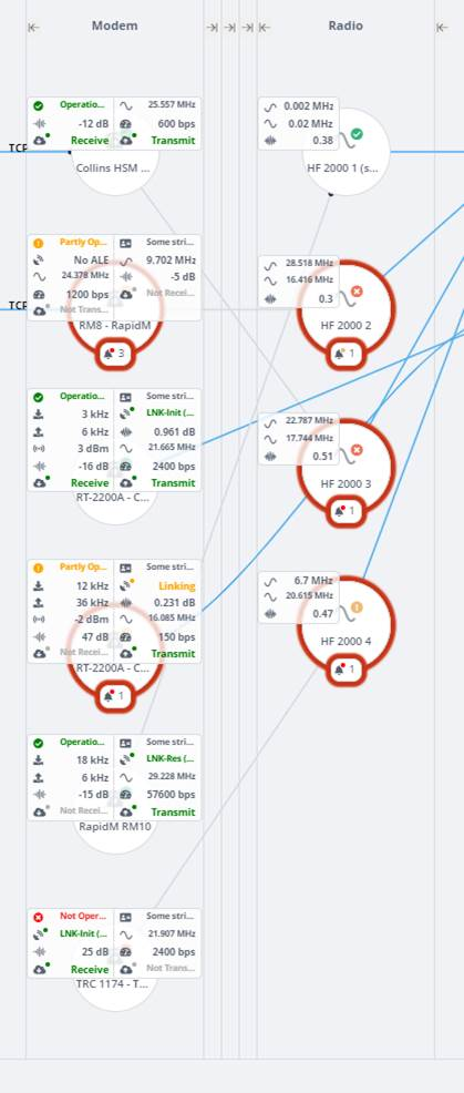
Red/Black provides support for all of the modems (Collins, RapidM, Thales) supported by Isode’s Icon-5066 product. It is useful for the operator to be able to monitor quite a few modem parameters:
- Operational status is shown, as the large number of parameters obscure the standard display.
- Transmit and receive status shown as separate parameters, highlighted in green when active.
- Current operational speed.
- SNR on reception, which is helpful to observe link quality.
- Transmit frequency. Technically, this is a radio parameter, but modern modems know and control this. Receive frequency may be different and is a separate parameter not shown by default on the top screen.
- For modems with ALE support the ALE status and active ALE peer is shown.
- For wideband modems the Tx and Rx bandwidth are shown.
These values give a clear picture of what is going on
Red/Black supports two radios: the Collins RT-2200A, which is a modem radio (and shows both modem and radio parameters) and the Leonardo HF 2000. The latter shows:
- Tx and Rx frequencies
- Voltage Standing Wave Ratio (VSWR) which is a key operational parameter, that allows easy detection of issues with power amplifier and antenna components.
Two red side services are of particular importance as they provide the final point in the communication chains where it make sense to enable/disable communication in order to support black side reconfiguration. The first of these is Icon-5066 (Isode’s STANAG 5066 server), which multiplexes applications onto an HF circuit. Red/Black top level UI for Icon-5066 is shown below.
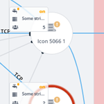
Icon-5066 shows on the top screen:
- STANAG 5066 Address of the node.
- Number of connected SIS clients.
- Whether the clients are flow controlled. Flow control will be applied in a busy system, so this is a useful operational metric.
The operator can enable and disable Icon-5066 nodes, to facilitate communication chain reconfiguration.
Red/Black can also monitor and control M-Switch, Isode’s messaging switch which supports email and military messaging over HF.
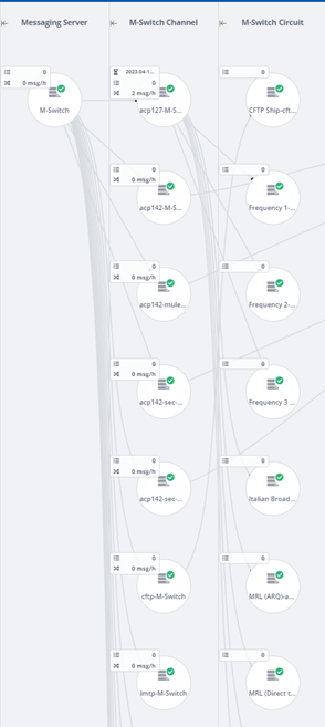
It can be seen that a single M-Switch is represented with a hierarchy of channels and circuits, as M-Switch is too complex to represent as a single Red/Black object. This hierarchy is generated by the M-Switch driver from the M-Switch configuration.
Modern HF messaging protocols operate over STANAG 5066, but ACP 127, in particular broadcast circuits, can connect directly to a modem. Red/Black can enable/disable M-Switch channels and circuits, which is important for ACP 127 circuit reconfiguration.
Messaging is the dominant bulk application used over HF. Red/Black shows message transfer rates and queue sizes, which enables the operator to detect message build-up, which might lead to HF circuit management activity or to message queue management.
Authentication and Roles
Red/Black servers require authentication and authorization to access. This is done using OAuth, which is used in conjunction with Isode’s M-Vault product which supports OAuth and users provisioned using Isode’s Cobalt provisioning product. This is described in more detail in the Isode OAuth whitepaper.
Users will authenticate to Red/Black with their own credentials and be provisioned with one of three roles:
- Administrator. Full rights to make changes and set up system configuration.
- Operator. Rights to make some changes, associated with operational management.
- Viewer. Read only access.
This reflects a model where the primary users will be operators who will make changes that can be fully controlled from Red/Black and appropriate modifications for a running system. The operator function is considered in more detail below.
Note that users on Red side and Black side will be authenticated independently. There is no authentication across the Red/Black boundary.
Communication Chains & Other Configurations
Many monitored devices will be able to form part of a communications chain. Red/Black is designed to monitor and control systems where the primary devices are linked in communication chains. There are three types of communication link shown by Red/Black:
- Fixed link. This reflects a link that is externally configured, such as a cable connecting two boxes. A Red/Black administrator will configure Red/Black to reflect this link.
- Application controlled link, where the application administrator will configure a link that is picked up by Red/black. This is the approach used with M-Switch.
- Operator controllable link. This reflects a link which can be configured by making changes to managed devices, for example by configuring a TCP connection. This type of link is controlled by Red/Black operators, which enables an operator to modify the communication chain using Red/Black.
Administrator Configuration
Red/Black has a configuration mode, which can be selected as an alternative to the device mode that is used when monitoring and controlling devices.
Administrator configuration is where an administrator modifies Red/Black connectivity to reflect physical (or externally configured) device connectivity.
This screenshot shows a PA connected to an antenna. The administrator can remove this connection and use the UI to connect the PA to another antenna. Note that devices in the communication chain are grouped in columns of similar types of devices, which makes it convenient to modify the communication chain.
Operator Configuration
In order for an operator to reconfigure a communications chain, it is necessary to have devices connected using mechanisms that can be configured by an operator. Red/Black supports two such mechanisms. Red/Black UI makes clear to the operator which changes can be made and which links are not modifiable by the operator.
The first approach is to use devices which map from the cabled connection to TCP. Use of such devices enables operator switching of configuration. Two places where this might be used:
- Audio switching, to give operator controlled connections between modem and radio.
- RF switching, to give operator controlled connections between radio and power amplifier.
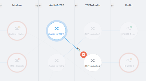
This screenshot shows use of an operator configured TCP link to provide operator reconfiguration between modem and radio using Audio/TCP convertors.
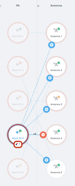
The second operator mechanism is support of configurable switches, which can be used in several places in the communications chain. This is provided as a generic mechanism, with one specific switch, the IES Antenna Switch, supported by the Red/Black SNMP driver. The IES antenna Switch is used in the following examples.
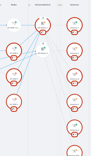
This example shows two Antenna Switches providing connectivity between radios and antennae. Administrator connection configuration is used to set up the physical connectivity of the switches.
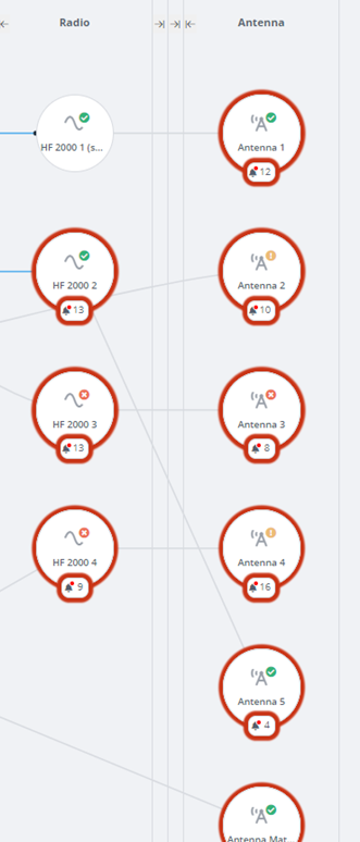
The Antenna Switch column can be hidden in the Red/Black display. When this is done, Red/Black shows the logical connectivity through the switches: which radio is connected to which antenna. This logical connectivity is usually going to be the most useful view.
Note that column hiding is a generic Red/Black capability, which enables operator focus on key device types. In the above screenshots, a PA column is also hidden.
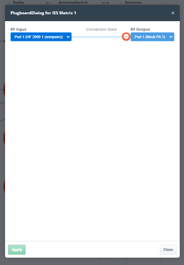
The operator can configure switch connectivity using the above UI, which is accessed from the switch icon.
Standalone Devices
Red/Black can also monitor and control devices which are not in the communication chain, as shown in the following screenshot.
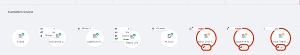
These devices can be completely independent or associated with one of more other devices. Some examples:
- Isode Servers, which are not part of the communication chain, but provide support to servers which are. The screenshot shows M-Vault Directory Server and Cobalt provisioning server being monitored.
- SNMP (Simple Network Management Protocol) managed devices associated with the communications chain. The screenshot shows SNMP monitoring of an Uninterruptible Power Supply (UPS), a host and a printer. Further information is provided in the Isode white paper SNMP Devices in Red/Black.
- Other types of device. The screenshot shows examples: Door Sensor; Fire Alarm, Thermometer. These are configured as example devices with mock drivers.
Device Monitoring and Control
A primary goal of Red/Black is to monitor and control devices. The top level view in Red/Black shows a full list of devices, each of which has a “traffic light” status and key parameters shown on the top screen In typical operation, most devices will be “green” (operating without error), so the high level view can be used to identify devices with issues. Devices can be selected to get more detailed information on a device and to control parameters, as shown below:
The core of the device display is a set of parameters associated with the device, grouped according to function. This includes:
- Generic information about the device, such as a description.
- Read only parameters provided by the device, such as VSWR.
- Parameters that can be set on the device by the Red/Black operator, such as transmission frequency. Editable parameters are indicated with a pencil icon.
- Parameters shown on the top screen are marked in yellow.
- Running Since. Reporting on how long the device is known to have been running.
There are a number of actions that can be controlled from the top screen, dependent on the device.
- Refresh. Send a request to the device to provide all parameters. This is supported by all device drivers.
- Reset. Instruct the device to perform a reset.
- Power Off. Instruct the device to turn off.
- Enable/Disable. This instructs the device to be active or not.
The Enable/Disable is key to building communication chains. Typically the change will begin with a device towards the application end of a communication chain (e.g., ACP 127 circuit or STANAG 5066 server) being disabled. Disabled devices are clearly marked in the UI, Then the rest of the communication chain will be assembled, and any necessary parameters under operator control set in the devices in the communication chain. When the communication chain is ready, the device at the start of the chain will be enabled again.
Alerts
Devices are able to issue alerts of varying severity. Low severity alerts can be used to provide informative information that may be helpful to the operator and high severity alerts can warn of problems that need attention. There are three types of alert:
- Alerts from the device, provided through the device driver.
- Alerts from Red/Black, typically relating to device driver failure.
- Alerts from Rules, for example to alert the operator to a parameter or status being abnormal.
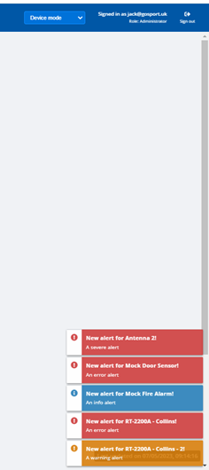
Alerts are shown to the Red/Black operator in a number of ways. As shown below, all arriving alerts are shown as a pop-up. This can draw immediate operator attention.
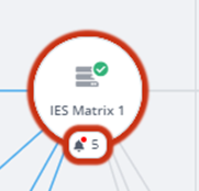
At the same time, new alerts are associated with the relevant device. The UI shows clearly that there are alerts, the number of pending alerts and the highest alert severity. The operator can go from this UI to examine pending alerts.
The next screenshot shows alert detail for a device
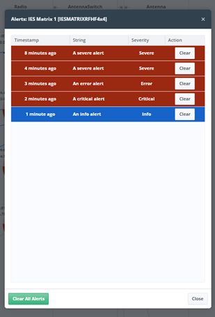
This UI allows the operator to clear alerts that have been handled and also to easily clear all alerts. This allows the operator to manage alerts and device issues.
Rules
In a future release, Red/Black will add a generic rules capability that can be used to provide extended alerts and other actions. Some examples of how this capability can be used:
- When a device parameter reports a value outside of a configured range, the operator is alerted.
- Alerts can also apply between devices. For example if an Antenna has a configured frequency range, an alert can be generated if a radio in the communication chain is set to a frequency outside that range.
- Rules can also lead to actions. For example if a thermometer associated with a device records a value above a certain level, the device will be turned off.
Abstract Devices
Red/Black is designed to monitor and control a very wide range of devices, from radios to servers such as Isode’s M-Vault directory server. It is not intended as a replacement for vendor-supplied management tools. Rather it gives basic monitoring and control of certain key parameters which might be needed by an operator taking an overall view of the system.
Central to the Red/Black design is the ideal of an Abstract Device specification which is an XML representation of the status and control parameters of a given device. The Red/Black UI is driven by Abstract Device specifications, so that the UI will fully adapt to any new device types that are added. This makes it straightforward to add new devices, which can be done by defining a new abstract device type without requirement to make any UI changes.
Devices are provisioned by adding a list of actual devices, each referencing the Abstract Device type of the device in question.
Complex devices, such as Isode’s M-Switch, can be represented as a hierarchy of devices, with the parent device only provisioned in Red/black and subsidiary devices created from the devices own configuration.
Product Architecture

The Red/Black architecture is shown above. The primary deployment model of Red/Black is with one server on each side of a Red/Black boundary. The goal of this is to enable operators Red side to monitor and control devices Black side. Both Red and Black side servers can monitored and configured with a standard Web browser. Devices are monitored and controlled through device drivers which are external to the core Red/Black server.
Separation between Red and Black sides is achieved by using a pair of XML Guards which act as application level data diodes:
- One XML guard controls flow of status information from Black to Red.
- The other XML guard controls flow of control messages from Red to Black.
The XML Guards are configured to ensure that only allowed information flows in each direction. Red/Black has a generic XML Guard design that could be used with any XML Guard, but it is primarily intended for use with Isode’s M-Guard product.
Red/Black can be used as a single server to monitor and control locally connected devices. This can be appropriate in some scenarios where there is no significant separation of Red and Black side function.
Device Drivers
For every device to be monitored/controlled in Red/Black there needs to be an Abstract Device specification and a device driver that supports that specification. Device Drivers use a simple protocol to talk to a local Red/Black server, which is specified to make it straightforward to write drivers. Isode provides a number of device drivers with Red/Black, in particular:
- Drivers for Isode server products. This enables straightforward support of communication chains that include Isode applications.
- Drivers for Modems/ALE Units supported by Icon-5066. This currently includes Collins and RapidM devices.
Isode also supports four generic drivers:
- Mock Driver. This can be used with any abstract device and it fakes behaviour of the device. It enables easy testing of abstract device specifications and communication chains without the need to use real devices or to write drivers.
- Null Driver. Sometimes a communication chain will include a device which it is not possible to monitor (e.g., a Crypto box). The Null driver can be used in a communication chain so that such devices appear in the Web UI monitoring view, despite the fact that they are not actually monitored or controlled by Red/Black.
- TCP Connect Driver. This connects to a device using TCP to provide a basic operational or not operational status value. This can be used with many applications.
- SNMP Driver. SNMP used to be an important way to monitor and control devices. Although it is of decreasing importance, Red/Black provides a driver that enables configurable use of SNMP(v3) to monitor and control devices that provide this support. Further information is provided in the Isode white paper Managing SNMP Devices in Red/Black.
Because device drivers use a standard protocol to talk to the Red/Black server, they can be written in any language. Isode provides a reference open source implementation available under an open source licence on Github. This includes a “mock radio device” with a Web UI and a C++ driver for that mock radio device. This is to facilitate third party development of device drivers.
An open device interfaces specification enables Isode partners and customers to develop device drivers. Isode is also happy to undertake development of specific device drivers.
Conclusions
This white paper has given an overview of Red/Black. With the exception or Rules Engine (planned for Release 2.1) all of the capabilities described are available in the current release (R2.0).
This paper has shown how Red/Black can monitor and manage devices across a secure boundary and how Red/Black enables monitoring and management of the HF Communications Chain.
Whitepaper Licensing
Isode whitepapers are licensed under a Creative Commons Attribution-ShareAlike 4.0 International License
![]()
Browse Related Whitepapers
